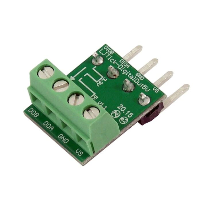
LJTick-DigitalOut5V
Converts 3.3V digital outputs to 5V digital outputs. Easily control 5V relays, or interface with a 5V logic device.
- Output only
- Source or sink 50mA or more
- Up to 800kHz
- Interfacing with 5V logic circuitry
NOTE: When the LabJack digital I/O is configured as an input, the DigitalOut5V accessory will output logic low.
Common Applications
- Controlling relays that require 5V logic signals.
Screw Terminal Descriptions
VS: This is the same 5 volt output as the VS terminals on the LabJack itself. This is an output terminal, not an input. It can be used to provide 5 volt (nominal) power as needed.
GND: Same as LabJack ground (GND).
DOA/DOB: These lines are the converted 5V logic lines.
The AND gate has Schmitt trigger inputs (i.e. hysteresis), which help avoid rapid toggling if a noisy signal slowly changes state.
The AND gate is powered by 3.3 volts from a regulator. An input of 0 to 1.0 volts will cause the output of the AND gate to be 0 volts. An input of 2.3 to VS (nominally 5.0) volts will cause the output of the AND gate to be 3.3 volts.
The output amp is powered by VS & GND, and is set up with a gain of x1.5. Thus the 3.3 volt high output of the AND gate will result in a 5.0 volt output from the amp, assuming a light load and assuming that VS is at least 5.0 volts.
If the DIO connected to the tick's input is set to output-high, the tick's output will be high. It the DIO is set to output-low, the tick's output will be low. If the DIO is set to input, the tick's output will be low (due to the pull-down resistors on the inputs). This last fact can be useful when the DIO is configured to go to output-low at power up, as there is usually a brief time where the line will be input before the configuration takes effect.
| Parameter | Conditions | Min | Typical | Max | Units |
| Supply Voltage | 3.5 | 5.25 | Volts | ||
| Supply Current | No loads | 1.5 | mA | ||
| Operating Temperature | - 40 | 80 | °C | ||
| Input Range | Normal | 0 | VS | Volts | |
| Max | -0.5 | VS+0.5 | Volts | ||
| Input to cause Logic high | 2.3 | Volts | |||
| Input to cause Logic low | 1.0 | Volts | |||
| Logic High Output | VS = 5.0V | 5.0 | Volts | ||
| Logic Low Output | 0 | Volts | |||
| Logic High with Load | VS = 5.0, 50 mA load | 4.6 | Volts | ||
| Output Drive Current (1) | Sink or Source | 50 | mA | ||
| Rise Time Delay | 70 | ns | |||
| Fall Time Delay | 90 | ns | |||
| Rise Time | 380 | ns | |||
| Fall Time | 460 | ns | |||
| Max Frequency (2) (3) | 760 | kHz |
