DRV8833 Dual Motor Driver Carrier

With an operating voltage range from 2.7 V to 10.8 V and built-in protection against reverse-voltage, under-voltage, over-current, and over-temperature, this driver is a great solution for powering small, low-voltage motors.
Texas Instruments’ DRV8833 is a dual H-bridge motor driver IC that can be used for bidirectional control of two brushed DC motors at 2.7 V to 10.8 V. It can supply up to about 1.2 A per channel continuously and can tolerate peak currents up to 2 A per channel for a few seconds, making it an ideal driver for small motors that run on relatively low voltages. Since this board is a carrier for the DRV8833, we recommend careful reading of the DRV8833 datasheet. The board ships populated with SMD components, including the DRV8833, and adds a FET for reverse battery protection.
This board is very similar to our DRV8835 dual motor driver carrier in operating voltage range and continuous current rating, but the DRV8835 has a lower minimum operating voltage, offers an extra control interface mode, and is 0.1″ smaller in each dimension; we also carry a DRV8835 dual motor driver shield that is easy to use with an Arduino. The DRV8833 has a higher peak current rating (2 A per channel vs 1.5 A), optional built-in current-limiting, and no need for externally supplied logic voltage.
Features
- Dual-H-bridge motor driver: can drive two DC motors or one bipolar stepper motor
- Operating voltage: 2.7 V to 10.8 V
- Output current: 1.2 A continuous (2 A peak) per motor
- Motor outputs can be paralleled to deliver 2.4 A continuous (4 A peak) to a single motor
- Inputs are 3V- and 5V-compatible
- Under-voltage lockout and protection against over-current and over-temperature
- Reverse-voltage protection circuit
- Current limiting can be enabled by adding sense resistors (not included)
Using the motor driver
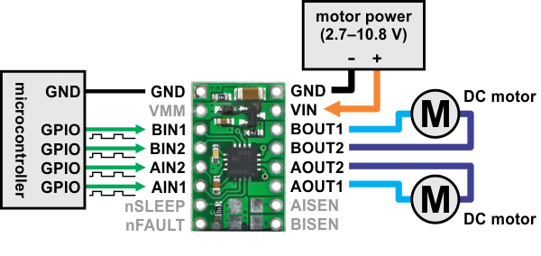 |
| Minimal wiring diagram for connecting a microcontroller to a DRV8833 dual motor driver carrier. |
|---|
In a typical application, power connections are made on one side of the board and control connections are made on the other. The nSLEEP pin is pulled high on the board and can be left disconnected if you do not want to use the low-power sleep mode of the DRV8833. Each of the two motor channels has a pair of control inputs, xIN1 and xIN2, that set the state of the corresponding outputs, xOUT1 and xOUT2; pulse width modulated (PWM) signal can be applied to each of these inputs. The control inputs are pulled low internally, effectively disabling the motor driver outputs by default. See the truth tables in the DRV8833 datasheet for more information on how the inputs affect the driver outputs.
The nFAULT pin is an open-drain output that is driven low by the chip whenever an over-current, over-temperature-or under-voltage condition occurs. Otherwise, it remains in a floating state, so you will need to connect an external pull-up resistor (or use a microcontroller input with its built-in pull-up enabled) if you want to monitor fault conditions on the driver.
| Size: | 0.5" x 0.8"¹ |
| Weight: | 1 g¹ |
| Motor driver: | DRV8833 |
| Motor channels: | 2 |
| Minimum operating voltage: | 2.7V |
| Maximum operating voltage: | 10.8V |
| Continuous output current per channel: | 1.2A² |
| Peak output current per channel: | 2A |
| Continuous paralleled output current: | 2.4A² |
| Reverse voltage protection?: | Yes |
-
Dimension diagram of the DRV8833 Dual Motor Driver Carrier (208k pdf)
-
3D model of the DRV8833 Dual Motor Driver Carrier (3MB step)
-
Drill guide for DRV8833 Dual Motor Driver Carrier (31k dxf)
This DXF drawing shows the locations of all of the board’s holes.
