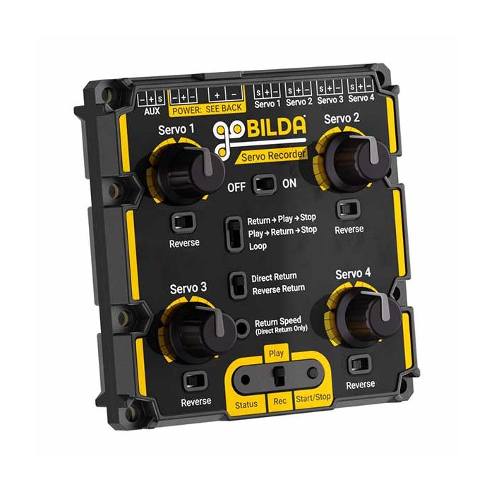
Bilda 4 Channel Servo Recorder
Record and play back multiple servos’ movements with the 4 Channel Servo Recorder!
It allows you to control up to four servos with a customizable recording up to 26 minutes in duration. Beyond simply recording and playing back servo movement, the Servo Recorder can fine-tune the playback to your project by allowing you to choose when and how servos return to their original positions.
Each of the four channels can be modified to a user-defined range of motion, as well as altered for reversed movement relative to the turning of its control knob. These features and more make the Servo Recorder a fantastic solution for getting exactly the repeated movement you want out of multiple servos. It’s perfect in animatronics assemblies, robotics projects, and pan and tilt systems!
Servo Connection
Four servo ports allow you to put up to four servos under the Servo Recorder’s control.
Voltage Input
The Servo Recorder can be powered by a DC input voltage between 5 and 15V. The XT30 connector is the primary power input port; however, if you are using a battery with a connector similar to that of a servo (TJC8), you may plug it into two of the three pins at the top of the board. Make sure to use only one of the available power inputs at a time.
⚠️VOLTAGE WARNING:The voltage you power the Servo Recorder with will be passed on to the servos. DO NOT use a voltage that is higher than a connected servo is rated for. Sending a voltage higher than a servo is rated for will result in damage to the servo.
Servo Recording and Playback
It’s easy to record and play back servo motion with the Servo Recorder. Just put the “Play/Rec” switch in the “Rec” position, then push the “Start/Stop” button. A blinking red “Status” LED will let you know your servos are being recorded. Move your servos via the control knobs. Push the “Start/Stop” button to end your recording at any point up to 26 minutes since the recording began, and voilà–you’ve recorded the servos’ movement!
To play back the recording, move the “Play/Rec” switch to “Play”, then push the “Start/Stop” button. Your servos will dance to every direction you provided them. All you need to do is sit back and watch them go!
Servo Return Settings
Different playback and position return options are selectable via the middle switches. These allow you to choose the method and speed at which servos return to their initial positions, as well as whether or not your recording stops or repeats. You can learn about these options and more in the User Manual.
PWM Range Customization
Each servo connected to the Servo Recorder can be constrained to a user-defined range of motion. It’s easy to set these ranges, and there’s no computer required! Just follow these steps:
- Power off Servo Recorder and put the “Play/Rec” switch in the “Rec” position. Plan for your servos to move during the next step. If you have a servo arm or linkage that could bind or cause damage to your build, consider removing it at this time.
- Press and hold the “Start/Stop” button and turn the Servo Recorder on. Continue to hold the button until the Status LED begins to blink orange. Release the button, and the Status LED will turn solid orange.
- Turn the control knobs so that your servos are all in locations within the ranges you wish to program.
- Press and release the “Start/Stop” button. The Status LED will change from solid orange to blinking orange, signifying that you are now programming the ranges of each of the four servos.
- Turn the knobs as much or as little as you would like to set the endpoints of each servo channel. Any knob that is not rotated during this time will cause its particular channel to default to the maximum PWM range of 500µs-2500µs.
- Once you have moved each of the 4 servos as desired, press the “Start/Stop” button. The Status LED will turn solid red, signifying that programming is complete and you have exited the range programming mode.
Resetting the ranges to the factory defaults can be achieved by repeating steps 1-6 without moving the knobs in step 5. Changing the ranges of the servos will also change the ranges used in the current recording.
Mounting
Thru-holes on the goBILDA® pattern allow you to fasten the Servo Recorder to your build. The holes’ nut-capturing hex counterbores provide for easy one-tool installation!
| Weight | 84g |
| Input Voltage Range (Limit) | 5-15VDC (Do not supply a higher input voltage than that for which your servos are rated). |
| Default PWM Range | 500μs - 2500μs |
