Pololu 5V, 2A Step Up/Down Voltage Regulator S13V20F5
This tiny synchronous switching step-up/step-down regulator efficiently produces 5 V from input voltages between 2.8 V and 22 V. Its ability to convert both higher and lower input voltages makes it useful for applications where the power supply voltage can vary greatly, as with batteries that start above but discharge below 5 V. The extra-compact board measures 0.35″ × 0.475″, has a typical efficiency of 85% to 95%, and can supply typical continuous output currents between 1 A and 2.5 A depending on the input voltage.
Features
- Input voltage: 2.8 V to 22 VOutput voltage: 5 V with 3% accuracy
- Typical maximum continuous output current: 1 A to 2.5 A, depending on input voltage (see the maximum continuous output current graph image)
- Typical efficiency of 85% to 95%, depending on input voltage and load (see the efficiency graph image no. 5)
- 10 mA to 20 mA typical no-load quiescent current (see the quiescent current graph image
- Input under-voltage lockout and output over-voltage protection
- Soft-start feature limits inrush current and gradually ramps output voltage
- Over-current protection and over-temperature shutoff
- 5 A output current limit
- Fixed switching frequency of ~500 kHz
- Double-sided assembly for extra-compact size: 0.35″ × 0.475″ × 0.22″ (8.9 mm × 12.1 mm × 5.6 mm)
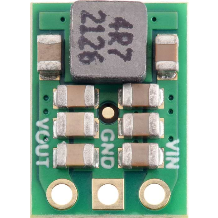
Connections
The step-up/step-down regulator has just three connections: the input voltage (VIN), ground (GND), and the output voltage (VOUT). The input voltage, VIN, powers the regulator. Voltages between 2.8 V and 22 V can be applied to VIN. VOUT is the regulated output voltage.These through-holes are arranged with a 0.1" spacing along the edge of the board for compatibility with standard solderless breadboards and perfboards and connectors that use a 0.1" grid. A 3x1 straight male header strip and a 3x1 right-angle male header strip are included, and you can solder in the one that gives you your desired board orientation. Alternatively, you can solder wires directly to the board for the most compact installations.
Typical efficiency
The efficiency of a voltage regulator, defined as (Power out)/(Power in), is an important measure of its performance, especially when battery life or heat are concerns.
Maximum continuous output current
The maximum achievable output current of the regulator varies with the input voltage but also depends on other factors, including the ambient temperature, air flow, and heat sinking. The graph below shows maximum output currents that the regulators in the S13VxF5 family can deliver continuously at room temperature in still air and without additional heat sinking.
Quiescent current
The quiescent current is the current the regulator uses just to power itself, and the graph shows this as a function of the input voltage.
LC Voltage Spikes
When connecting voltage to electronic circuits, the initial rush of current can cause voltage spikes that are much higher than the input voltage. If these spikes exceed the regulators maximum voltage, the regulator can be destroyed. If you are connecting more than about 15 V, using power leads more than a few inches long, or using a power supply with high inductance, we recommend soldering a 33 μF or larger electrolytic capacitor close to the regulator between VIN and GND. The capacitor should be rated for at least 35 V.
| Size: | 0.35″ × 0.475″ × 0.22″1 |
| Weight: | 0.8 g1 |
| Minimum operating voltage: | 2.8 V |
| Maximum operating voltage: | 22 V |
| Continuous output current: | 2 A¹ |
| Output voltage: | 5 V |
| Reverse voltage protection?: | N |
| Maximum quiescent current: | 20 mA³ |
| Output type: | fixed 5V |
Notes :
1. Without included optional headers.
2. Typical continuous output current at 5 V in. Actual achievable continuous output current is a function of input voltage and is limited by thermal dissipation. See the output current graph under the description tab for more information.
3. With no load. Actual quiescent current depends on input voltage. See the quiescent current graph..
