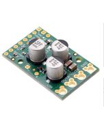
TB67H420FTG Dual/Single Motor Driver Carrier
This breakout board makes it easy to use Toshiba’s TB67H420FTG brushed DC motor driver, which can operate in either dual-channel mode for independent bidirectional control of two motors or single-channel mode for driving one motor with increased current.
It has a wide operating voltage range of 10 V to 47 V and can deliver a continuous 1.7 A to each motor channel, or 3.4 A in single-channel mode.
Dimensions*
- Size- 1.2" x 1.0"
- Weight: 3.5g
The TB67H420FTG from Toshiba is an H-bridge motor driver IC that can be used for bidirectional control of one or two brushed DC motors at 10 V to 47 V. It can supply up to about 1.7 A continuously to each of two separate motors or about 3.4 A to a single motor, and it can tolerate peak currents up to 4.5 A per channel (dual) or 9 A (single) for a few seconds, making it a good choice for small- to medium-sized motors that run at higher voltages.
Included hardware
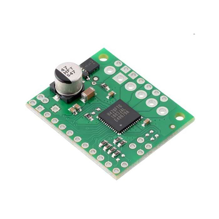
This product ships with all surface-mount components—including the TB67H420FTG driver IC—installed as shown in the product picture. However, soldering is required for assembly of the included through-hole parts: one 1×20-pin breakaway 0.1″ male header and three 2-pin, 3.5 mm terminal blocks (for board power and motor outputs).
Features
- Single- or dual-channel H-bridge motor driver (can drive one or two DC motors)
- Motor supply voltage: 10 V to 47 V
- Output current:
- up to 1.7 A continuous (4.5 A peak) per motor in dual-channel mode
- up to 3.4 A continuous (9 A peak) in single-channel mode
- Configurable current chopping actively limits motor current to 4.5 A per channel (dual) or 9 A (single) by default; can be lowered with external resistors or voltage sources
- No separate logic supply needed; inputs are 3V- and 5V-compatible
- Flexible input interface provides several options for control
- Under-voltage lockout and protection against over-current/short-circuit and over-temperature
- Open-load detection
- Carrier board adds reverse-voltage protection up to 40 V
- Active-low error outputs indicate over-current, over-temperature, or open-load condition
- Compact size (1.0″ × 1.2″)
- Exposed solderable ground pad below the driver IC on the bottom of the PCB
| Motor Driver | TB67H420FTG |
| Motor Channels | 2 |
| Minimum operating voltage | 10V |
| Maximum operating voltage | 47V* |
| Continuous output current per channel | 1.7A |
| Continuous paralleled output current | 3.4A |
| Reverse voltage protection? | Y* |
*Note: Reverse voltage protection only works up to 40 V