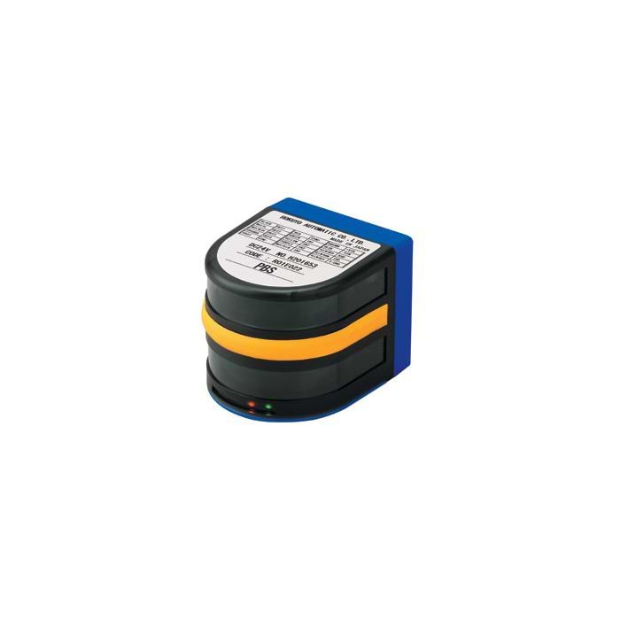
HOKUYO PBS-03JN Infrared Range Finder
The PBS-03JN has a wide scanning area and is a popular alternative to laser range-finders in indoor environments.
The sensor is popular due to its low cost, low power consumption and light weight design.
-
Indoor Environments
The PBS-03JN is a good alternative to laser range-finders in indoor environments.
The sensor is popular due to its low cost, low power consumption and light weight design.
- Low cost infrared range finder
- Angular Resolution 1.8°
- Responce time 180msec or less
- Angular scanning range 217.8°
- Range 200 to 3000mm
- Power consum. 24Vdc @250mA
- RS232 interface
- Size 75 x 70 x 60mm
- Weight 500g
Features
- This was 60% smaller than PB9 about cubic volume. Scanning angle(Detection area) is increased to 180° and detectable dead zone is getting smaller.
- Operation principle is that semicircular field is scanned by LED(lambda = 880nm) and the coordinates is calculated by measuring distance to object and its step angle and then it detects obstacle in setting area.
- Detection area can be set by PC(RS-232C). Detection distance with 3 steps output for each area can be set.
- Changeover for Max. 15 kinds of detection area set by PC can be made by outer bit input.
| Model Number | PBS-03JN | |
| Power Source | 24VDC (Allowable range 18 to 30VDC including ripple) | |
| Current Consumption | 250mA or less (100mA or less when emission stops) Except for I/O terminal current and rush current (500mA) | |
| Light Source | Infra-red LED | |
| Detectable Object and Detection area |
White paper with 300×300mm (Placed in parallel with sensor projection surface), 0.2 to 3m×2m (Origin point is scanning center position) but within scanning angle 180° |
|
| Area Setting | Output 1 | It is free to set from 0 to 10m for optical axis direction with 7 points pointer. |
| Output 2,3 | Linear setting to progressive direction, fan-shaped setting to optical axis direction, Percentage (%) setting against output 1 pointer | |
| 2 scanning mode | When each detecting area setting, it sets individually for each output. | |
| Hysteresis | 10% or less of detection distance (it is not getting 60mm or less) | |
| Output | Photo-coupler/NPN open-collector output (30VDC 50mA or less) Output 1,2,3 : output OFF when detecting within area, trouble output : output ON when normal operation* | |
| Input(Input 1 to 4) | Photo-coupler input(Anode common, each input current 4mA or more), This can changes setting detection area. | |
| Detecting area setting |
It set the area No. by Input 1, 2, 3 and 4 It stops the emission by getting all Input 1, 2, 3 and 4 to ON (OFF : H level input, ON : L level input) |
|
| Output response time | 180msec or less (Scanning speed 1 rev./100msec) 280msec or less when 2 scanning mode (but except for 100msec, area changeover time) | |
| Input response time | Input taking-in cycle : 1 scanning time (100msec) | |
| Input Responce Time | Input taking-in cycle : 1 scanning time (100msec) (1msec when choosing emission-stop by outer input | |
| Lamps |
Power lamp (Green) : Flickered when trouble Output 1, 2 and 3 lamp (Orange) : Lights up when detected in area |
|
| Connection method | Lead wire 1m long | |
| Ambient illuminance(note) | Halogen/mercury lamp : 10,000lx or less, Fluorescent lamp : 6,000lx or less | |
| Ambient temperature/humidity | -10 to +50 degrees C, 85?RH or less (Not condensing, not icing) | |
| Vibration resistance | 10 to 55Hz, double amplitude 1.5mm Each 2 hour in X, Y and Z directions | |
| Impact resistance | 490m/s2, Each 10 time in X, Y and Z directions | |
| Impact resistance | 196m/s2 Each 10 time in X, Y and Z directions | |
| Protective structure | IP64 (IEC standard) | |
| Materials | Front case : Polycarbonate, rear case : ABS | |
| Life | 5 years (motor life) | |
| Weight | Approx. 500g | |
* Output 1 to 3 show the state that it is detecting object when this output executed
Note) It may malfunction when receiving strong light such as sun light etc.
External Dimensions
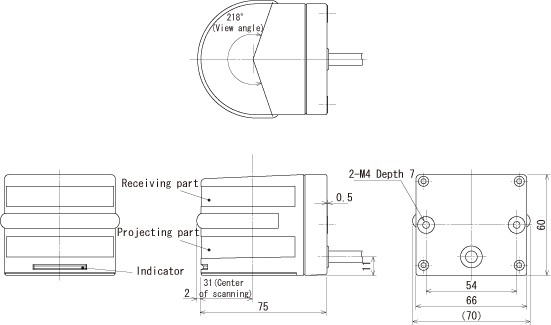
Note: Detecting area is 180°
Input/Output Circuit
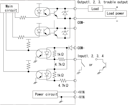
Connections
| Colours | Signals |
| Black | Output 1 |
| White | Output 2 |
| White (Blue) | Output 3 |
| Orange | Trouble Output |
| Gray | Output common minus |
| Red | Input common plus |
| Green | Input 1 |
| Yellow | Input 2 |
| Purple | Input 3 |
| White (Yellow) | Input 4 |
| White (Purple) | Input 5 |
| Brown | +VIN |
| Blue | -VIN |
| Yellow (Red) | Serial input (RXD) |
| Yellow (Green) | Serial output (TXD) |
| Yellow (Black) | Serial GND |
Note) Input/output direction is mentioned on the basis of PBS.
